Anisotropy – Stretching noise
By specifying a rectangular region from which the noise function is sampled, a stretched noise effect can be achieved. For example, a rectangular tile with anisotropic noise sampling renders as seen in Figure 9.

Figure 9 Anisotropic tiles
The corresponding texture and bump maps are

Figure 10 Anisotropic per tile noise on rectangular tiles
For the sake of completeness, the input file that was used to generate the images was
outputFileName /Users/attilazsaki/Desktop/yellow_square_tile_localnoise04.tif
textureWidth 2048
textureHeight 2048
tiledAreaWidth 10.0
tiledAreaLength 10.0
tileWidth 2.0
tileLength 0.6
groutWidth 0.02
tileColorGlobalColorType variable
tileColorGlobalColorNoiseType perlin
tileColorGlobalColor 1.0 0.94509803921569 0.57254901960784 1.0
tileColorGlobalColorLowSide 1.0 0.92549019607843 0.42745098039216 1.0
tileColorGlobalColorHighSide 1.0 0.96470588235294 0.56078431372549 1.0
tileColorGlobalNoiseXMin 0.0
tileColorGlobalNoiseYMin 0.0
tileColorGlobalNoiseXMax 10.0
tileColorGlobalNoiseYMax 10.0
groutColorColorType variable
groutColorColorNoiseType random
groutColorColor 0.5 0.5 0.5 1.0
groutColorColorLowSide 0.4 0.4 0.4 1.0
groutColorColorHighSide 0.6 0.6 0.6 1.0
tileColorLocalColorType variable
tileColorLocalColorNoiseType perlin
tileColorLocalColor 1.0 0.94509803921569 0.57254901960784 1.0
tileColorLocalColorLowSide 1.0 0.92549019607843 0.42745098039216 1.0
tileColorLocalColorHighSide 1.0 0.96470588235294 0.56078431372549 1.0
tileColorLocalNoiseXMin 0.0
tileColorLocalNoiseYMin 0.0
tileColorLocalNoiseXMax 5.0
tileColorLocalNoiseYMax 20.0
tileColorLocalOctaves 8
tileColorLocalPersistence 1.0
tileBumpNoiseAlternateColorType variable
tileBumpNoiseAlternateColorNoiseType perlin
tileBumpNoiseAlternateColor 1.0 1.0 1.0 1.0
tileBumpNoiseAlternateColorLowSide 1.0 1.0 1.0 1.0
tileBumpNoiseAlternateColorHighSide 1.0 1.0 1.0 1.0
tileBumpNoiseAlternateNoiseXMin 0.0
tileBumpNoiseAlternateNoiseYMin 0.0
tileBumpNoiseAlternateNoiseXMax 2.0
tileBumpNoiseAlternateNoiseYMax 2.0
tileBumpNoiseAlternateOctaves 2
tileBumpNoiseAlternatePersistence 0.25
randomTileOrientation false
randomTileNoiseStartPoint true
generateBumpMap true
tileBumpNoiseAlternate true
tileDiscolorationMapGenerate false
blurFinalImage false
useTileXOffset
tileXOffset 1.01
In this example note that the tile size is rectangular and so is the tileColorLocalNoise sampling region. It is from 0,0 to 5,20. Also note that the tile offset was used to alternate the tile locations. The tile offset was calculated using half of the tile width (2.0*1/2) plus half of the grout line width (0.02*1/2) to get 1.01.
Discoloration maps – grime, grunge and dirt
So far our tiles were clean. However, it is easy to use noise again and overlay a noise map on top of our tile color texture. Ideally, this noise is a slowly varying one, with only parts of it showing, e.g. in some regions the original tile color shows through, while other parts are darkened with our grime color, as seen in Figure 11.
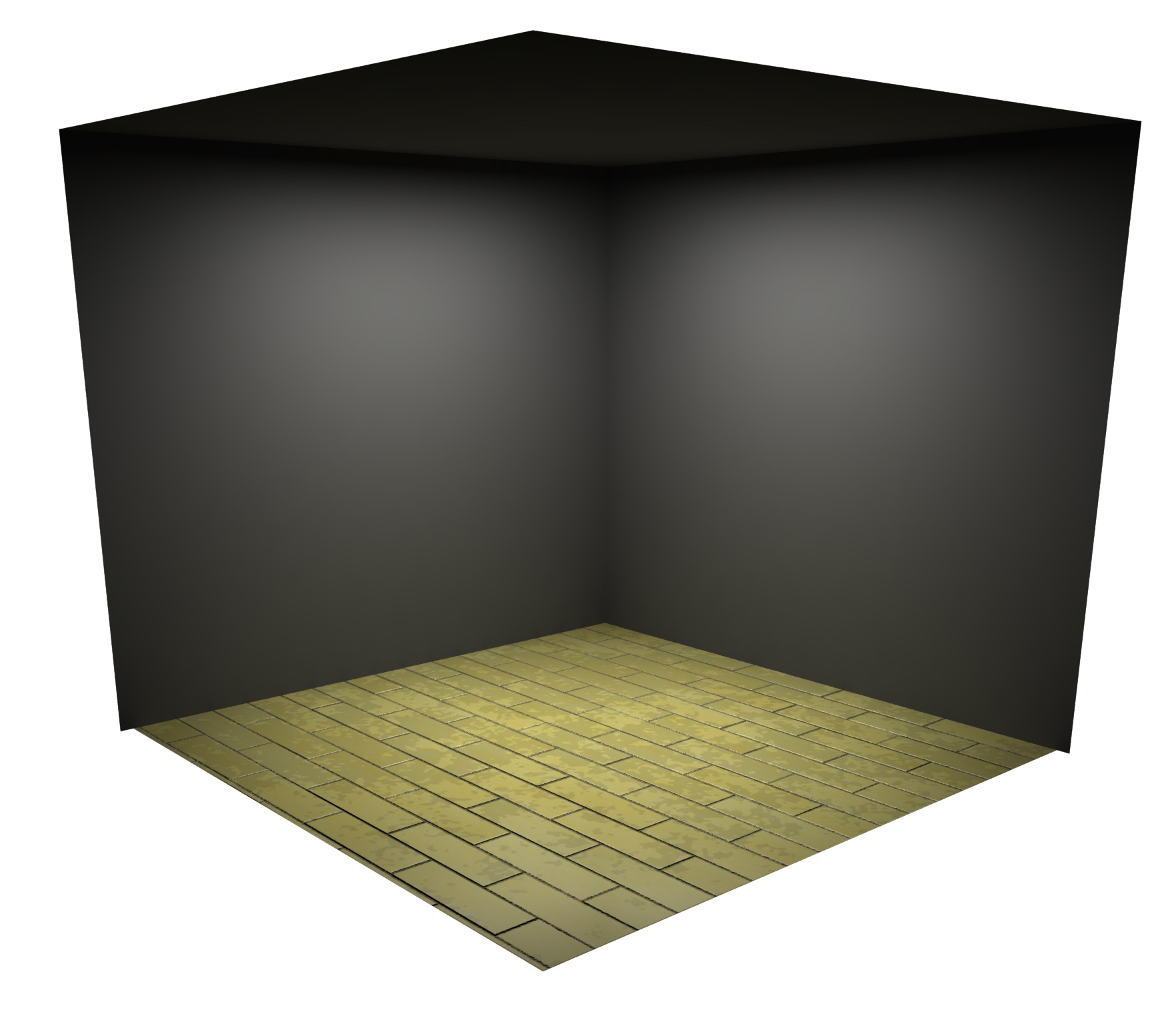
Figure 11 Discoloration map applied to the tiles
The input file is same as the previous example, but this time a section describing the discoloration map was added, as follows
tileDiscolorationMapColorType variable
tileDiscolorationMapColorNoiseType perlin
tileDiscolorationMapColor 1.0 1.0 1.0 1.0
tileDiscolorationMapColorLowSide 1.0 1.0 1.0 1.0
tileDiscolorationMapColorHighSide 1.0 1.0 1.0 1.0
tileDiscolorationMapNoiseXMin 1.0
tileDiscolorationMapNoiseYMin 1.0
tileDiscolorationMapNoiseXMax 1.15
tileDiscolorationMapNoiseYMax 1.15
tileDiscolorationMapOctaves 7
tileDiscolorationMapPersistence 1.0
tileDiscolorationMapThresholdLower 0.50
tileDiscolorationMapThresholdUpper 1.0
tileDiscolorationMapThresholdPercentReduction 10.0
tileDiscolorationMapGenerate true
Note that the color descriptor has the same components as the previously presented ones, with the addition of a few new parameters; tileDiscolorationMapThresholdLower, tileDiscolorationMapThresholdUpper and tileDiscolorationMapThresholdPercentReduction. These three parameters establish a bound on the noise values, anything below the lower threshold or anything above the upper threshold will not affect the underlying tile color. Values within the threshold bounds are uniformly darkened by the specified percentage. The resulting color texture and bumps maps are
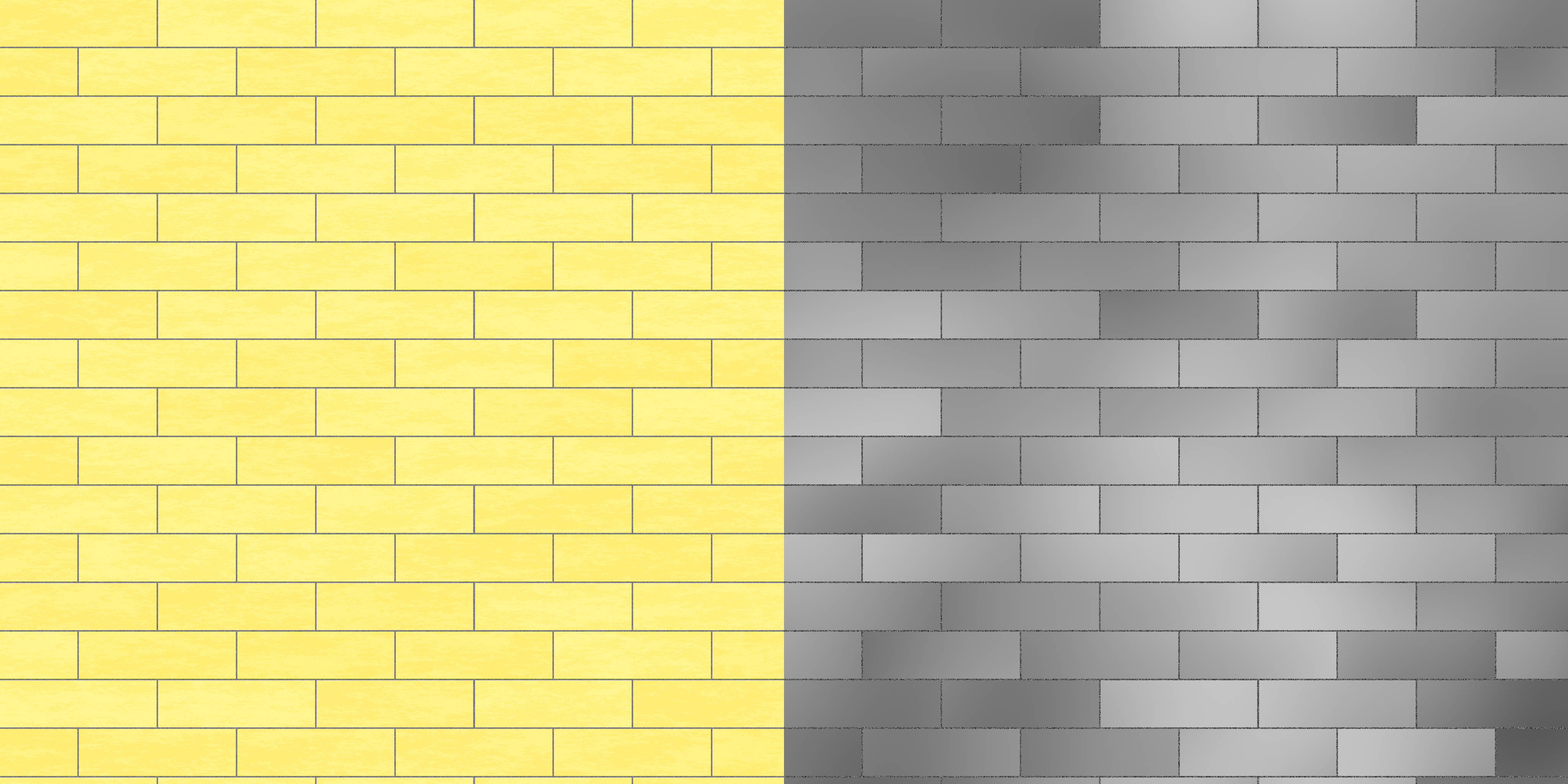
Figure 12 Discoloration or grime map applied to our tiles
Bumpy bump maps
Thus far the bump maps were either different for each tile, yet constant within a tile or had only a smoothly varying noise, characteristic of a perhaps not-so-carefully-laid, unleveled tiles. If the noise is made more high frequency, resembling that of often found in natural stone, then bumpiness of the surface can be part of the visual appeal of a tile. Consider a large stone tile, for which the color of the tile is governed by a Perlin noise and so is the associated bump map, as shown on Figure 13. The base color of the tile varies from tile to tile and the local, per-tile color is varied as a high-frequency noise. Coupled with the bump map, the stone gives a pitted, rough surface.
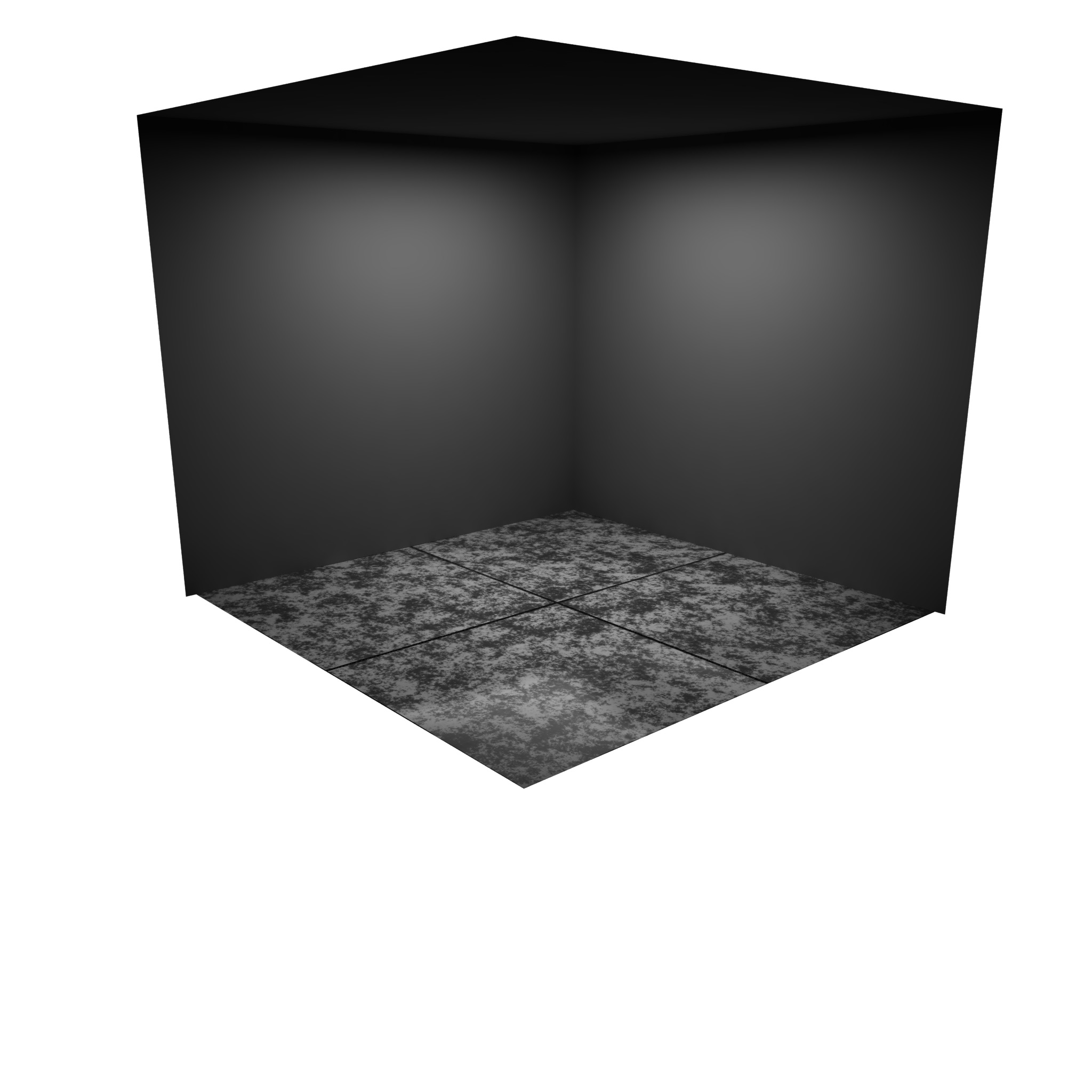
Figure 13 Stone tiles with high-frequency noise for bump maps
The associated texture and bump map is shown on Figure 14. Note that the underlying noise function is the same for both the texture map and the bump map. The differences are the colors used in the interpolation of the final color. The texture map has more distinct black/white bands, while the bump map varies smoothly.

Figure 14 Texture and bumps maps for Figure 13, showing a pitted, rough tile surface
The input file used in generating the maps in Figure 14 is as follows
outputFileName /Users/amzs/Desktop/perlin_noise01.tif
textureWidth 2048
textureHeight 2048
tiledAreaWidth 10.0
tiledAreaLength 10.0
tileWidth 2.5
tileLength 2.5
groutWidth 0.02
tileColorGlobalColorType variable
tileColorGlobalColorNoiseType perlin
tileColorGlobalColor 0.5 0.5 0.5 1.0
tileColorGlobalColorLowSide 0.0 0.0 0.0 1.0
tileColorGlobalColorHighSide 1.0 1.0 1.0 1.0
tileColorGlobalNoiseXMin 0.0
tileColorGlobalNoiseYMin 0.0
tileColorGlobalNoiseXMax 10.0
tileColorGlobalNoiseYMax 10.0
tileColorLocalOctaves 8
tileColorLocalPersistence 1.0
groutColorColorType variable
groutColorColorNoiseType random
groutColorColor 0.5 0.5 0.5 1.0
groutColorColorLowSide 0.4 0.4 0.4 1.0
groutColorColorHighSide 0.6 0.6 0.6 1.0
tileColorLocalColorType solid
tileColorLocalColorNoiseType perlin
tileColorLocalColor 0.5 0.5 0.5 1.0
tileColorLocalColorLowSide 0.0 0.0 0.0 1.0
tileColorLocalColorHighSide 1.0 1.0 1.0 1.0
tileColorLocalNoiseXMin 0.0
tileColorLocalNoiseYMin 0.0
tileColorLocalNoiseXMax 10.0
tileColorLocalNoiseYMax 10.0
tileColorLocalOctaves 8
tileColorLocalPersistence 1.0
tileBumpNoiseAlternateColorType variable
tileBumpNoiseAlternateColorNoiseType perlin
tileBumpNoiseAlternateColor 1.0 1.0 1.0 1.0
tileBumpNoiseAlternateColorLowSide 1.0 1.0 1.0 1.0
tileBumpNoiseAlternateColorHighSide 1.0 1.0 1.0 1.0
tileBumpNoiseAlternateNoiseXMin 0.0
tileBumpNoiseAlternateNoiseYMin 0.0
tileBumpNoiseAlternateNoiseXMax 2.0
tileBumpNoiseAlternateNoiseYMax 2.0
tileBumpNoiseAlternateOctaves 2
tileBumpNoiseAlternatePersistence 0.25
randomTileOrientation false
randomTileNoiseStartPoint true
generateBumpMap true
tileBumpNoiseAlternate false
blurFinalImage false
This concludes Part II of the article. Stay tuned for Part III!