
The development of sim|FEM grew out of the need to analyze problems in geomechanics as part of my research at Concordia University. The program is mainly written by me with the aid of some of my students as part of their research projects. The program is based on finite element theories specifically to analyze displacements and stresses occurring in geologic media. The goal of the program is the computation of displacements and stresses occurring in soils or rocks when subjected to self-weight (gravity) or some form of disturbance, such as the process of excavation, mining or tunnelling. In addition to stress analysis, sim|FEM can compute flow through porous medium as modelled using Laplace’s equation to represent groundwater flow. Both 2D and 3D elements are implemented in sim|FEM for stress analysis, while thus far only 2D elements exist for groundwater flow.
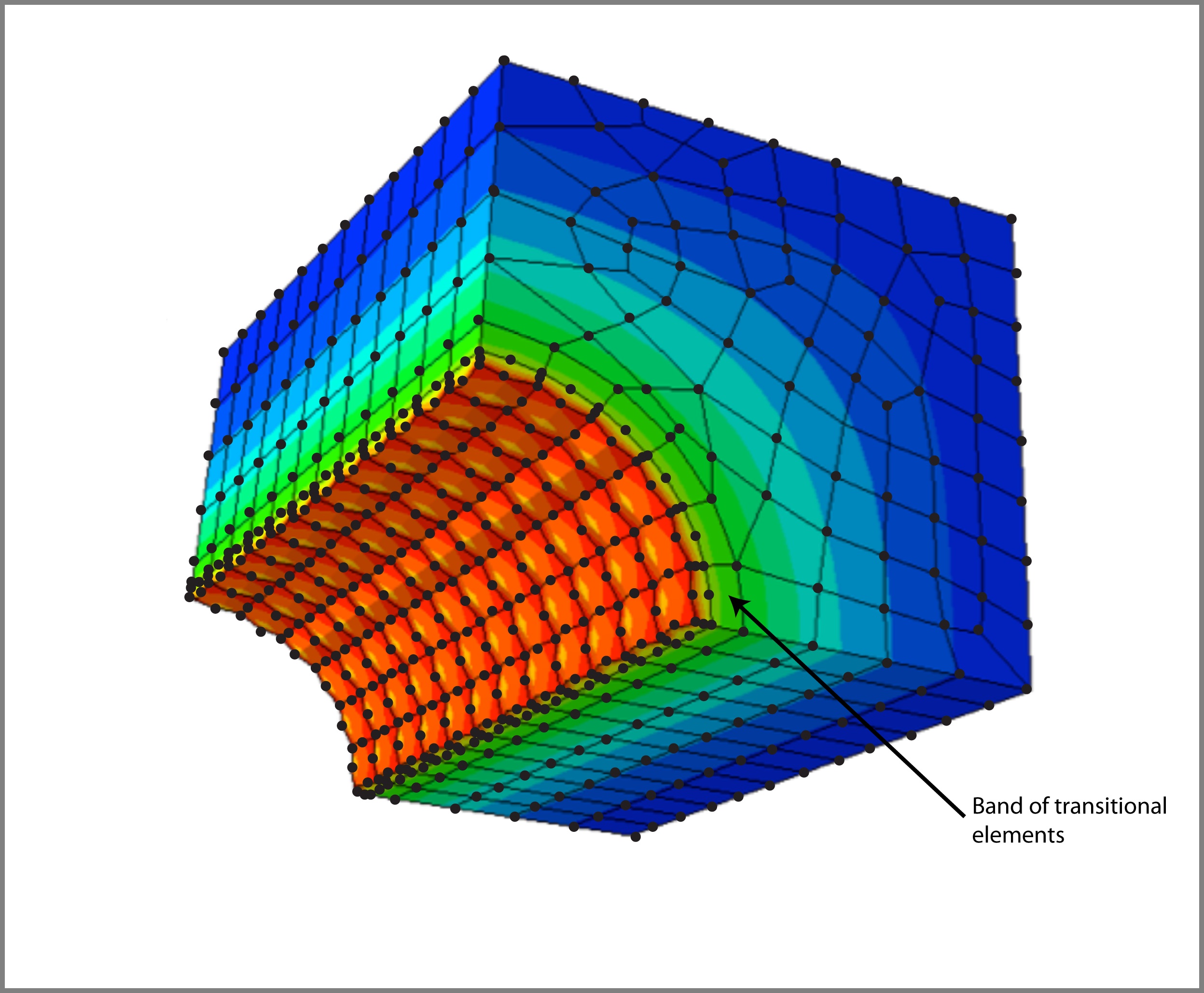
sim|FEM was conceived to fill the gap existing in commercial software offerings with regard to the ease of expandability and adding new features, while having a full control over the source code. Some of my work is related to the development and use of so called transitional elements. These elements connect meshes with first order (e.g. 4-noded quadrilaterals) to second order (e.g. 8-noded quadrilaterals) using elements that on one of their sides (or faces) have first order interpolation (2 nodes per edge) and on the adjacent side (or face in 3D), second order interpolation (3 nodes per edge). To learn more about the topic, see some of my papers.
Since one of my interests is software optimization for performance, sim|FEM serves as a testbed for the development of efficient solvers arising in the solution of finite element problems. The use of both algorithmic acceleration and software libraries such as Apple’s Accelerate framework, Nvidia’s CUDA or OpenCL results is considerable speedups achieved. Some effort has been made to develop parallel solvers using OpenMP and MPI within sim|FEM, but those are not ‘officially’ avaliable.
The development environment for sim|FEM is C++ using Apple’s Xcode environment. Since only pure C++ is used, sim|FEM can be compiled on almost everything, even a coffee grinder, if it supports a C++ compiler. Seriously, it was successfully compiled, in addition to a Mac, under Windows’ Visual Studio, SGI’s MIPSpro compilers and gcc in Linux.
The following short sections illustrate the current, and ever evolving, capabilities of sim|FEM.
Element library
For groundwater flow analysis the following elements are currently implemented in 2D:
- 4-noded rectangle
- 3-noded triangle
- 6-noded triangle
- 4-noded quadrilateral
- 8-noded serendipidity quadrilateral
- 4-noded transitional triangle
- 5-noded transitional triangle
- 5-noded transitional quadrilateral
- 7-noded transitional quadrilateral
For displacement and stress analysis, the following elements are currently implemented in 2D:
- 3-noded triangle
- 6-noded triangle
- 4-noded quadrilateral
- 8-noded serendipidity quadrilateral
- 4-noded transitional triangle
- 5-noded transitional triangle
- 5-noded transitional quadrilateral
- 7-noded transitional quadrilateral
For displacement and stress analysis in 3D, the following elements are currently implemented:
- 8-noded hexahedron
- 20-noded hexahedron
- 12-noded transitional hexahedron
- 16-noded transitional hexahedron
All elements can be used in full or reduced integration mode where applicable for the element.
Material library
The material models in sim|FEM can model anisotropic groundwater flow, elastic material model for stress analysis and soil plasticity using a Mohr-Colulomb material model. I am aware that the number of material models is quite limited, but constitutive modelling is not one of my current research priorities. More material models will be implemented as need arises in the future.
Loading and boundary conditions
The usual loading and boundary conditions exist in sim|FEM. Groundwater flow can be defined as total heads or fluxes applied at any node of the model. For stress analysis in both 2D and 3D any of the displacements can be restrained or be specified along with nodal loads at any node. Specific to geomechanics, material self-weight acting as a body load can be specified as well. In situ stresses can be applied to the model using a stress block specifying the principal stresses in both 2D and 3D.
Solvers
Thus far the following solvers exist in sim|FEM. Each of these solution methods were implemented in C++ without relying on third party libraries. However, since I am an Apple guy, there exists a platform optimized version of each method using Apple’s Accelerate framework, which is based on various BLAS routines. The speedup is admirable, well done Apple!
- Gaussian elimination (using full matrix storage)
- Gauss-Seidel method (using full matrix storage)
- Gauss-Seidel method (using banded matrix storage)
- Conjugate Gradient method (using full matrix storage)
- Conjugate Gradient method (using banded matrix storage)
- Conjugate Gradient method (without assembling the global stiffness matrix)

Output
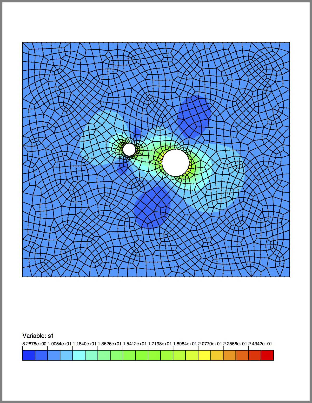
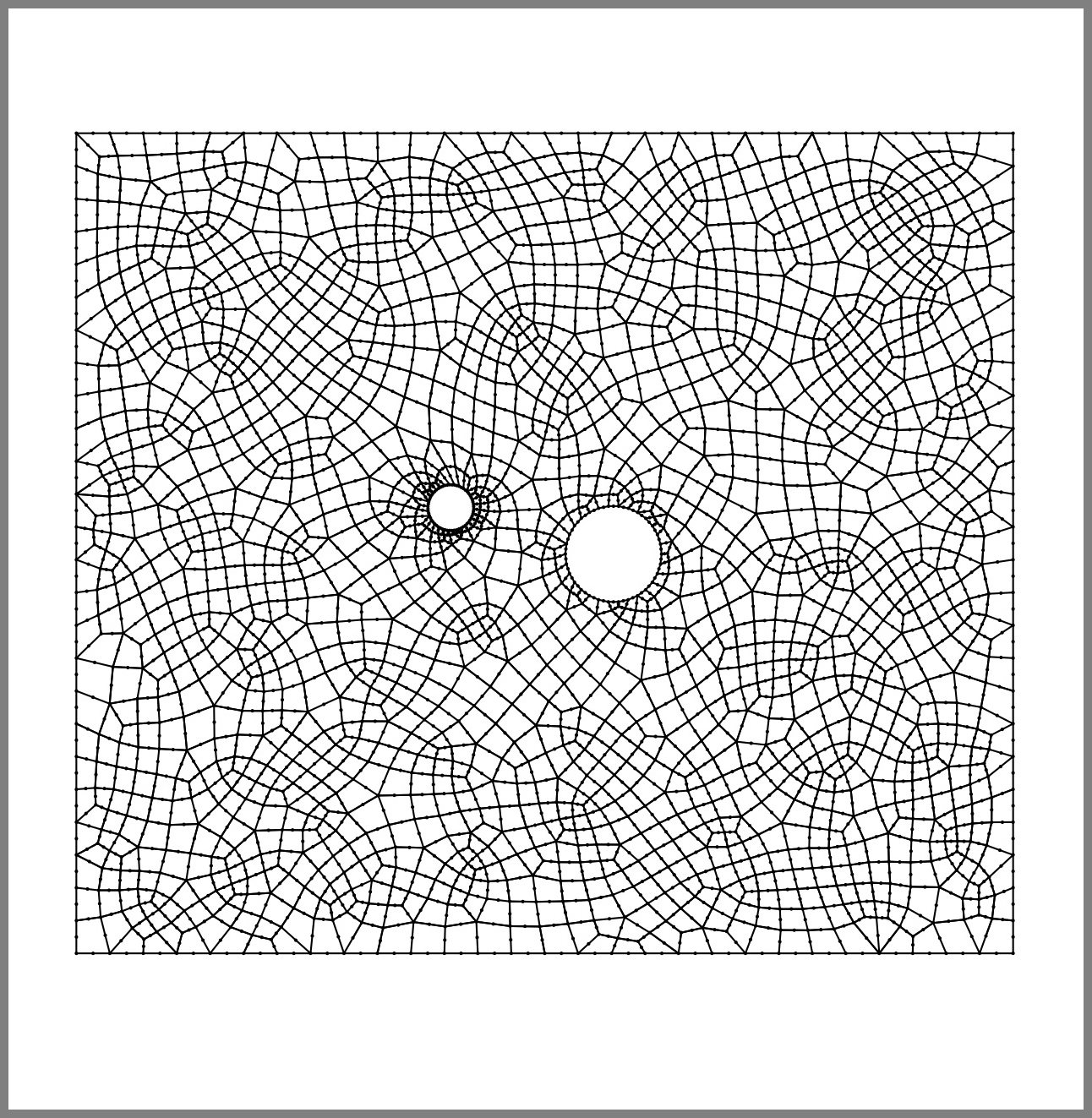
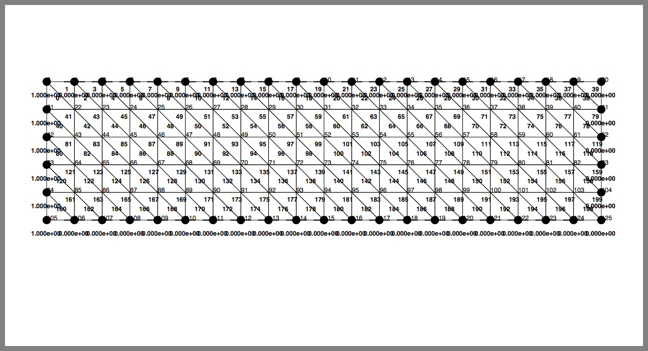
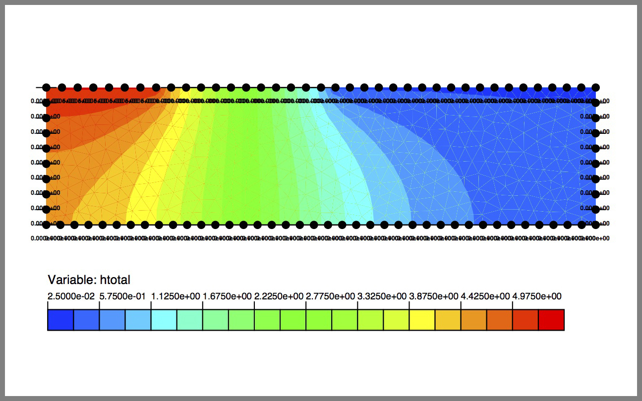
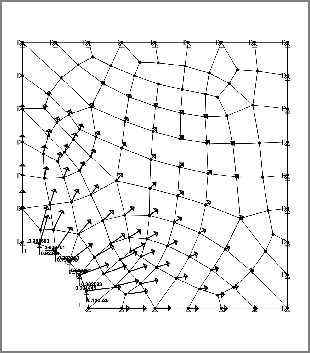
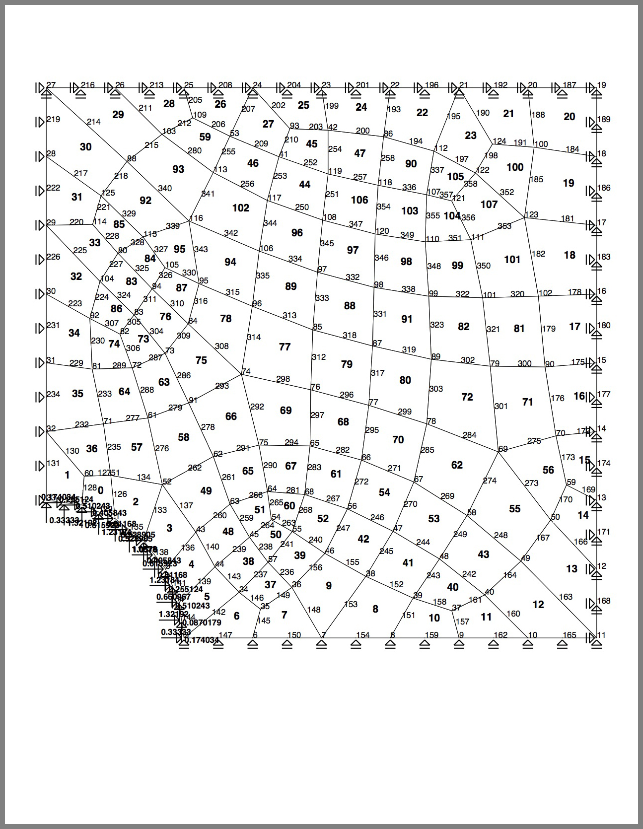
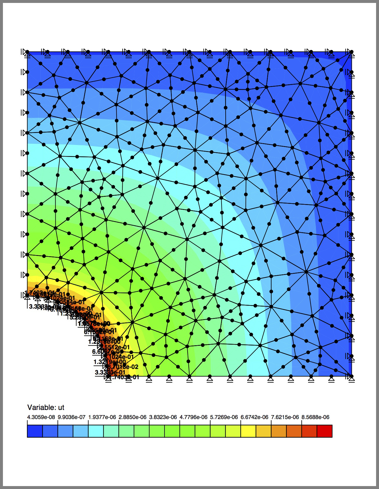
The philosophy regarding outputs generated by sim|FEM is simple; since it is an academic research code geared toward computation, the time to develop a graphical front end and visualization package cannot be justified at this point. Maybe if I have some free time and don’t know what else to do… In addition, results obtained from the program often illustrate some principle or point that has a high likelihood to appear in a publication. There is a strong pressure from publisher to include only high quality figures. Thus, sim|FEM outputs its results as PostScript files. The vector nature of PostScript enables resizing and changing the output images without any loss of quality. What appears on each page is completely scriptable, so the placement of a legend or font sizes for node and element numbering can be changed at will. sim|FEM is capable of generating plots of undeformed and deformed meshes, contour plots and vector plots of the following quantities;
- pressure and total head for groundwater flow
- displacements and stresses (principal and along any cartesian axis, both normal and shear), and strains (principal and along any cartesian axis, both normal and shear)
In addition to graphical output, sim|FEM can produce textual output for all variables along arbitrary lines across a model enabling the creation of plots in various other software packages.

Gallery of models
The following few representative examples illustrate the type of problems that can be analyzed using sim|FEM and the potential for graphical output.


All text and images copyright of A.M. Zsaki, 2014.